Introduction
Lifting binary code compiled to run on some computer architecture is a daunting task. It can be broken down into two steps:
- Decode a bit stream into an assembler instruction.
- Lifting - Describe the behavior of the instruction within the language of the target intermediate language (IL).
The second step requires the definition of such an intermediate language first.
A recent target required the PowerPC instruction set (including VLE instructions) to be added as a lifter front-end to our emulator and we shall use this architecture to illustrate the process of lifting. Given are the bytes below and the task of the lifter is to translate these bytes into one or more instructions in our IL:
88 01
This particular instruction decodes to
se_lbz r0,0x8(r1)
and, when executed, loads one byte from the memory at address r1 + 8 and places
the zero-extended value into r0. This behavior needs to be modeled by the IL.
For the IL in use, this amounts to the following instructions:
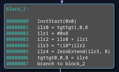
InstStart(0x0) is a pseudo instruction, which has some practical benefits
whenever a mapping of target instructions to IL instructions or host
instructions becomes necessary. The instruction at offset 1 loads 4 bytes at
offset 0 of register 1 of the target (tgttgt1,0,4). This is just r1. The
value is saved to the IL register ilr0. At offset 2, the constant 8 is loaded
into ilr1. The sum of these is stored in ilr2 and is equal to r1+8. The
result is used as address for an 8-bit wide load operation
in instruction 4. The result in ilr3 is zero extended by a pseudo instruction
and the resulting ilr4 is written to the target register 0 (at offset 0 and 4
bytes wide). This is just r0. This graph can be amended to include instrumentation,
e.g. for fuzzing.
Optimizations may be able to eliminate all of theses instructions, because the value may be known from a previous load or store operation and can be reused. Opportunities for optimizations become more probable, the more of the IL graph is known before execution. Optimizations are especially useful in fuzzing, when the code generated from the lifted IL is executed billions of times.
After optimization, the IL instructions are then either executed in an emulator, or, if speed is a major concern, translated/compiled for the host architecture.
To add a new lifter to QEMU, one has to implement the above steps in C. An example pull request adding a new architecture to the unicorn engine (which uses QEMU under the hood) can be observed here.
While new architectures are rare, it can be prohibitively complicated or expensive to add and support a new architecture to an existing legacy code base. Encountering bugs in these lifters can be very hard to identify and fix.
Other approaches exist. The software reverse engineering suite Ghidra employs the SLEIGH compiler to generate a lifter from a human readable specification file. SLEIGH compiles these specification files into a serialized instance of a lifter, which produces P-code, which is the name for the IL employed in Ghidra. The manual states
P-code is designed specifically to facilitate the construction of data-flow graphs for follow-on analysis of disassembled instructions.
While P-code was not designed specifically for emulation, support for emulating P-Code was exposed in Ghidra v9.1 (September 2019), because it can help the reverse engineer to better understand a piece of code by running it. This was also quickly employed in fuzzing. Airbus released Ghidralligator, which combines the lifter from Ghidra with the famous AFL1 fuzzer.
Translate to Emulate
Currently, fast emulation involves translating the lifted instruction into instructions that can be directly run on the host system. In QEMU, this part is handled by the Tiny Code Generator (TCG), which emits host instructions on a basic block basis. Constant folding is applied at this level and is - to our knowledge - the only optimization technique applied to the lifted instructions, trading runtime speed for latency. Any instrumentation used for fuzzing must be inserted during this step. This involves patching QEMU and maintaining the set of patches.
As opposed to QEMU, the Ghidra emulator only interprets the P-code and does not translate it to the host architecture, resulting in relatively slow execution speed.
Lift like the NSA
A vectorized emulator introduces several constraints, which we found painful to work around when working with P-code. The most important is that P-code intermediate registers can be of arbitrary size, whereas a vectorized instruction can only work on (maximum) 64-bit wide values and so the intermediate registers of our lifter must be restricted to 64 bits, too.
While we have had a proof of concept rewriting P-code to our own IL, we hit lots of roadblocks that would require us to maintain a set of patches for Ghidra. Hence, we set out to implement our own lifter framework, inspired by SLEIGH, but with vectorized emulation and fuzzing in mind. The framework now serves as the front-end for the vectorized emulator, which we employ in fuzzing campaigns.
The goal of the lifter framework is to make building a lifter easier and more flexible. Ideally the instrumentation and fuzzing techniques should depend as little as possible on the target architecture. SLEIGH achieves this by allowing to specify the architecture in a custom language. The language lets the implementer specify registers and instructions in a way that a disassembler and lifter can be conjured for any CPU architecture.
At the heart the framework lies the ID3 algorithm. The algorithm builds a decision tree which takes a byte stream as input and outputs one or more instructions that the bytes decode to. The tree is built by identifying a set of consecutive decisions (inner vertices) that lets the user descend down to the leaf, which hold one ore more instructions. The decision is defined by a range of bits, which are interpreted as an index into the array of children vertices. The algorithm uses a metric called Information Gain, to decide which bit ranges should be used in an attempt to find a solution that (hopefully) minimizes the depth of the tree.
This allows to compile an instruction definition from
// Defines variables based on a range
define op               (0,3)
define variable SD4     (4,7)
define variable Z       (8,11)
define variable X       (12,15)

// Attaches variables to registers
attach variables [X Z] [r0 r1 r2 r3 r4 r5 r6 r7]

// Define an alias for the memory location
sd4b: SD4(X) => X & SD4 { X + SD4 }

// Load with zero extend
:se_lbz Z,sd4b => op=0b1000 & sd4b & Z & X
{
    // Body: load 1 byte from memory at address sd4b
    // Since Z is a 32bit register, the value will be zero-extended.
    Z = [sd4b]:1
}
to a full IL graph by visiting the AST compiled from the body of the instruction definition and resolving constants and registers accordingly. Here, the bits have the following meanings:
- 0-3 (4 bits): must be equal to 0b1000 (or 8 decimal)
- 4-7 (4 bits): giving us an offset into a memory location
- 8-11 (4 bits): giving us the index into the attached array of registers, specifying the destination register
- 12-15 (4 bits): giving us another index, specifying the base register for the memory location
When writing down the two bytes from the introduction and splitting them into nibbles, we find:
1000 | 1000 | 0000 | 0001
Noting that this is a big-endian architecture, the first nibble (bits 0-3) is the op-code and holds the required value 8. The second nibble corresponds to the offset of the memory location, which is 8, too. The third nibble represents the index (0) into the register array for the destination register and resolves to r0. The last nibble corresponds to the index (1) of the base register for the memory location and resolves to r1. Since no other variables are used, it can deducted that the instruction is 2 bytes long. This is a simple example. More complex instruction sets require lots of additional features, like decoding bits depending on other bits (think of modrm/sib bytes), supporting prefixes (repz, lock, etc.) and so on. There sometimes exist ambiguities regarding the instruction encoding. For example, PPC ebook instructions and PPC VLE instructions have some overlap and can be interpreted according to both. It seems to be correct to prefer the VLE instructions when this happens, but we did not find this documented anywhere.
Finally, the IL instruction graph can be optimized, interpreted, analyzed, modified or jitted (Just In Time-compiled) to the host architecture and executed on bare metal.
Shoutout
We would like to explicitly credit Brandon Falk for the idea of a vectorized emulator. His streams and blog posts is what enabled all of the above in the first place.
-
American Fuzzy Lop ↩︎